
From the roof to the aquifer.

Everything a rainwater harvesting system needs — the catchment on your roof, the filters and storage in between, and the recharge structures in the ground.

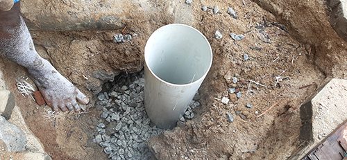
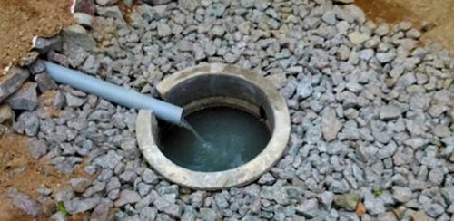
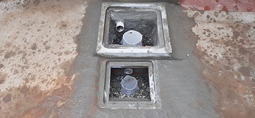
Filter bed of gravel around an inlet pipe inside a recharge chamber

How a system works

Components of a rainwater harvesting system

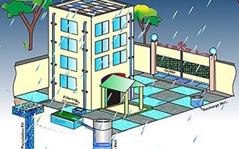
A rainwater harvesting system comprises components of various stages — transporting rainwater through pipes or drains, filtration, and storage in tanks for reuse or recharge. The common components involved in these stages are described below.

  1. Catchment
  2. Gutters
  3. Pipes
  4. Filter
  5. Storage
  6. Recharge
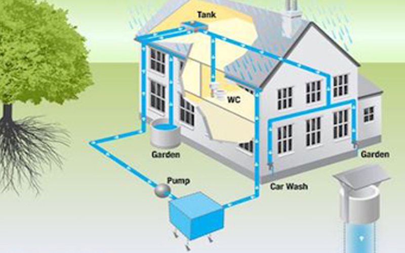
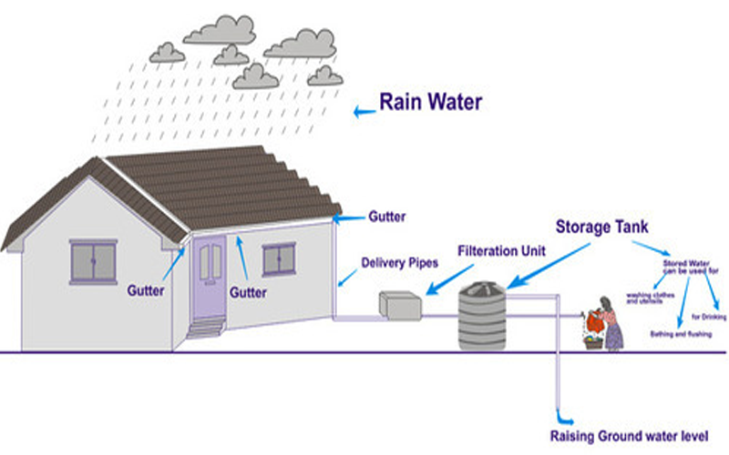
Diagram of a house: rain water runs from gutters through delivery pipes and a filtration unit into a storage tank, and down to raise the ground water level
Gutters, delivery pipes and a filtration unit feed the storage tank — with the overflow raising the ground water level.

The components

Seven parts, one system.

Every part of the journey, from the roof to the ground. Each system we build is sized to your roof, your soil and how you want to use the water.

01

Catchments

The catchment of a water harvesting system is the surface which directly receives the rainfall and provides water to the system. It can be a paved area like a terrace or courtyard of a building, or an unpaved area like a lawn or open ground.

A roof made of reinforced cement concrete (RCC), galvanised iron or corrugated sheets can also be used for water harvesting.
02

Coarse mesh

Fitted at the roof to prevent the passage of debris — so leaves and dirt are stopped before they reach the pipes and filter.

03

Gutters

Channels all around the edge of a sloping roof to collect and transport rainwater to the storage tank. Gutters can be semi-circular or rectangular and could be made using:

  • Locally available material such as plain galvanised iron sheet (20 to 22 gauge), folded to the required shapes.
  • Semi-circular PVC gutters, prepared by cutting pipes into two equal semi-circular channels.
  • Bamboo or betel trunks cut vertically in half.
04

Conduits

Conduits are pipelines or drains that carry rainwater from the catchment or rooftop area to the harvesting system. They can be made of any commonly available material, such as polyvinyl chloride (PVC) or galvanised iron (GI).

05

Filter

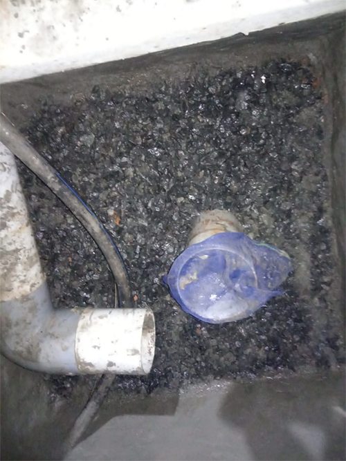
The filter removes suspended pollutants from rainwater collected over the roof. A filter unit is a chamber filled with filtering media such as fibre, coarse sand and gravel layers, removing debris and dirt before the water enters the storage tank or recharge structure.

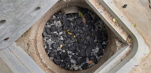
Charcoal can be added for additional filtration.

06

Storage facility

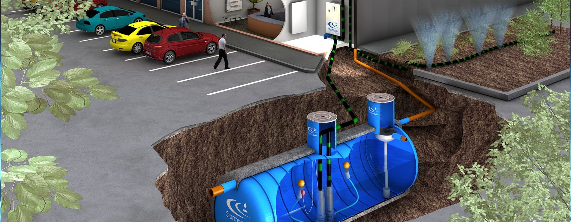
There are various options for the construction of storage tanks with respect to their shape, size and material of construction — above the ground or below it, sized to how much water you want to keep.

07

Recharge structures

Rainwater may be charged into the groundwater aquifers through any suitable structures, like dugwells, borewells, recharge trenches and recharge pits.

Some structures promote the percolation of water through soil strata at shallower depth (for example recharge trenches and permeable pavements), while others conduct water to greater depths, from where it joins the groundwater (for example recharge wells). At many locations, existing wells, pits and tanks can be modified as recharge structures — eliminating the need to build anything afresh.

Recharge solutions

Built to send rain back underground.

Typical specifications from our own designs. Every structure is sized to your site, soil and roof area.

Diagram of a 2 by 2 feet recharge chamber with a 10 to 15 feet slotted rain pipe View

Recharge pit

A compact chamber with a filter bed and a slotted PVC rain pipe that carries filtered rooftop water deep into the soil — ideal for homes and small plots.

Chamber
2 × 2 ft
Rain pipe
7″ slotted PVC
Depth
10–15 ft
Filter bed
Blue metal + charcoal
Diagram of a borewell recharge well with well ring, blue metal and charcoal layers, and a slotted PVC pipe View

Borewell recharge

A well ring around a slotted PVC bore pipe with layered filtration, directing rooftop water towards the aquifer.

Chamber cover
3 × 3 ft
Well ring
3 ft wide, 7 ft deep
Bore pipe
7″ PVC, 10–15 ft
Filter layers
Blue metal + charcoal
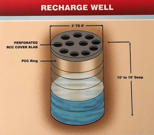
Recharge well diagram: 3 to 6 feet wide, 10 to 15 feet deep, PCC rings and a perforated RCC cover slab View

Recharge well

Stacked PCC rings under a perforated RCC cover slab form a large well that takes in heavy runoff and lets it soak into the ground.

Diameter
3′ to 6′
Depth
10′ to 15′
Lining
PCC rings
Cover
Perforated RCC slab
Diagram of percolation pits and a percolation trench around a building, with layers of sand over a pebble-filled bore View

Percolation pits & trench

Percolation pits linked by a trench around the building let water soak into the ground across a wide area.

Sand layers
0.7 m + 0.3 m
Pebble bore
Up to 6 m deep
Layout
Pits + perimeter trench
Best for
Large compounds

Who we build for

Systems for every building.

From a single house to a factory roof, the same principles apply — catch it, clean it, store it or send it back to the ground.

Diagram of a home connected to two recharge chambers and a well

Homes

Rooftop water is filtered into recharge chambers and your open well, keeping your own water source topped up.

Diagram of a building connected to a 6 by 4 feet pit and four 2 by 2 feet pits

Apartments & buildings

Larger roofs need more capacity — such as a 6 × 4 ft main pit feeding a row of 2 × 2 ft recharge pits.

Diagram of a recharge well connected to two 1000 litre tanks and a sump that supplies a school

Schools

A recharge well paired with 1000-litre storage tanks and a sump, so harvested rain supplies the campus.

Video cover: rain water harvesting — commercial, for factories and industries

Factories & industries

Commercial systems for large roofs and paved yards. Watch the video

Build your house with us.

Looking for the best rain water harvesting? Tell us about your site — the first consultation is free.